For the people with the skills and patience for Do-It-Yourself (DIY)
The Durso Standpipe™ design is perfect for coral reef display, marine fish only, or fresh water aquariums where you need a quieter display tank. However, there are a few important details that need to be brought up if you plan on making a Durso Standpipe™.
PVC Size to Use
My tank has a 1 inch bulkhead on the bottom glass where the water drains out. For this size hole, I recommend you use 1¼ inch Schedule 26 PVC for the standpipe. I do not recommend 1½ inch PVC as the larger fittings are much harder to fit inside overflow chamber (also called a weir). Secondly, there is no advantage in 1½ inch over 1¼ inch PVC when dealing with a 1 inch bulkhead — the bulkhead is the limiting factor for the amount of water that can drain out.
These instructions assume you will be constructing a standpipe for a 1 inch threaded bulkhead.
To Oversize or Not to Oversize
With 1 inch and smaller bulkheads the standpipe's PVC diameter needs to be larger than the bulkhead to work correctly. I get a lot of e-mail questions on why this is. Honestly, I’m not sure. Typically if you use 1 inch PVC pipe on a 1 inch bulkhead you get poor results. (Some exceptions with smaller low flow tanks.) Take my word on it and use 1¼ inch PVC pipe. For large tanks with 1.5 inch bulkheads and large return pumps however, there does not seem to be any need to oversize the standpipe for larger bulkheads. Bulkheads 1.5 inches and larger can use PVC pipe & fittings that match the size of the bulkhead. (I consider tanks in the 350 gallon and up good candidates for 1.5 inch bulkheads).
Parts of the Durso Standpipe
The bottom section:
If you have a threaded bulkhead, the first fitting is a 1 inch threaded male adapter which screws into the threaded bulkhead. Be sure to use Teflon tape on the threads, you want this to be a water tight seal. Note: A male adapter is only needed for threaded bulkhead.
Next, convert the 1 inch pipe to a 1 ¼ inch pipe using a reducer bushing. (There is a small section of 1 inch PVC pipe linking these two parts). The reducer bushing is then inserted into a coupling.
- If you have access to a reducing male adapter that is a good option to use -- It is 1 inch male by 1 ¼ inch insert fitting. Threaded style Durso Standpipes purchased from me will use this fitting.
- If you have a slip bulkhead then see if you have can get a reducing coupling -- It is 1 inch insert by 1 ¼ inch insert fitting. Slip style Durso Standpipes purchased from me will use this fitting.
The middle section:
Then the vertical PVC pipe is inserted in the coupling. The PVC pipe I recommend is Schedule 26 commonly called thin-wall PVC pipe. It is thinner, lighter and drains better than schedule 40 pipe. The height of this section of pipe varies depending on the parts you use and how tall your aquarium is. The end goal is that when completed, the top end-cap will be about equal to the upper rim of the aquarium.
I recommend PVC cement for this connection to keep it water tight.
The top section:
At the top of the standpipe is a 1¼ Tee fitting. This is attached to the standpipe with Teflon tape only. I suggest using about three wraps to get a good tight seal. Do not glue this fitting.
A special elbow connector called a “Street-ell” or “Street 90″ is then inserted and pointed directly downwards. This is the water intake, it will always be submerged. Since it is submerged, it can not suck in surface air.
Note: A street-ell allows the ell to be inserted directly into the Tee fitting without requiring a separate small PVC pipe length to connect the elbow and tee together. A standard PVC Elbow can be used but may not be as compact as the street-ell. To fit into the older style small AGA overflows, just trim the street ell connector down. Only about ¼ inch is needed for a gluing surface.
Use PVC cement to connect the Street-Ell to the Tee. On the top part of the Tee fitting, insert a small section of PVC pipe which should be glued in. Finally place an End-Cap fitting to top the unit. The End-Cap is held on with teflon tape.
Standpipe Air Hole
A very small, as small as I could make it (thickness of a toothpick), hole is drilled in the top of the End-Cap fitting. This allows some air to enter into the standpipe. This size air hole worked well for my setup, you will likely need to tinker with it. I would suggest starting with a 1/16 inch drill bit for the air hole in the End-Cap. If you find the water level in the chamber fluctuates quickly then the standpipe needs to suck in more air. Try a 5/64 inch drill bit to make the hole slightly larger — increasing the size if needed. Do not be surprised if you need to go as large as ¼ inch with the hole size. The lower the flow rate between display tank and sump the larger the hole size needed.
The hole on the top of the standpipe (in the End-Cap) is very important. Without the hole, a full siphon will be created and water will be sucked out of the overflow chamber too fast. The water level will drop below the intake and you will get a terrible air sucking noise. If you drill a hole and the water level still drops to far (making a sucking noise) then the hole is to small. Just make it slightly larger (see above) and the water level will raise. If you make the hole to large then the water level will be to high. (It should not overflow the tank as it will not get that high, but keep an eye on it). If the water level is too high you may need to replace the end-cap (they are cheap). Many people report that it is easier to tune with several smaller holes than a single larger hole.
Overflow Chamber Water Level
Ideally the water level in the overflow chamber will be about 1 to 2 inches lower than the display water level. This provides for gas exchange and prevents an organic film from building up on the water surface of the overflow chamber. If you designed it correctly, the water level in the overflow chamber will be a little lower than the display tank and the water level will be at about the middle of the Street-Ell fitting as pictured in the introduction page. If the water level is slightly higher, no big deal. As long as the overall water level in the chamber is lower than the display tank it is stable that is good enough.
The height of the Durso Standpipe™ is not critical. I would recommend the height of the end-cap (top of the Durso Standpipe™) to be about equal or slightly higher than the top plastic rim of the tank.
Exploded Parts List
The following is a break down of parts used to construct a Durso Standpipe. Only commonly used easy to find plumbing fittings are listed. Specialty fittings such as reducing male adapters and reducing couplings are not illustrated since these are not common fittings.
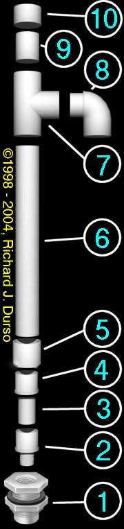 |
#10 - 1¼ PVC End-Cap with vent hole.
#9 - Connector made of 1¼ PVC. Glue to Tee, Teflon taped top for snug fit with End-Cap.
#7 - 1¼ PVC Tee. Do not glue this onto the standpipe. Use Teflon tape on the standpipe for a snug fit. This allows it to be removed for height adjustment or maintenance.
#6 - 1¼ PVC Pipe. Sized long enough to get the End-Cap just about equal to the upper rim of the display tank.
#5 - 1¼ PVC Coupling. The stand pipe and reducer bushing are glued to this part.
#4 - 1¼ to 1 inch reducer bushing.
#3 - Connector made of 1 inch PVC. This should be glued into the reducer bushing. If you have a slip bulkhead, this inserts directly into the bulkhead — use Teflon tape for snug fit into the bulkhead.
#2 - OPTIONAL: 1 Inch PVC Male adapter - only needed on threaded bulkheads. You may want to attach to connector with Teflon tape to allow for a quick yank removal from bulkhead. Use Teflon tape on threads before inserting into bulkhead.
#1 - Bulkhead. The opening at the bottom of your overflow chamber to allow water to drain out to the sump. This drawing shows a threaded bulkhead.
|