
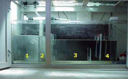
55 Gallon Acrylic Sump
Picture Taken March 1999 This is pretty close to my current sump configuration. My previous sumps were just way too small to handle a volume of about 2,500 gallons per hour. Each of the walls in the sump are called baffles. These baffles are needed to reduce the air bubbles reaching the return pumps. The light coming into the sump from above is from the tank lights above. This picture was taken before the sand bed was added to the tank. I use two 65w PowerCompact units above my sump to grow macro algae. I use a reverse daylight cycle to help stabilize pH. Updates since picture taken: I have since added one more baffle splitting chamber 1 in half, I removed the PVC overflow pipe and now have both flex tubes just empting into the far left side of the first chamber. |
|
This is a standard 55 gallon acrylic tank with four chambers:
The sump has 35 gallons of water in it - where I keep it at all times. |
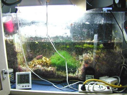
55 Gallon Acrylic Sump After Several Years
Picture Taken September 2001 This picture was taken about 2.5 years after the sump picture from above. As you can see the sump has become heavily coralline encrusted. I had to scrape the sump down just to get a picture of it. The sump lights are two Lights of America 65w Power Compacts which are more than able to grow Sargassum sp. and Chaetomorpha sp. which are macro algaes that work much better than Caulerpa as they do not go sexual and release toxins into the water. |
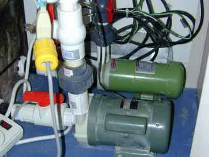
Dual Return Pumps
Picture Taken December 2000 I like alot of current in my tank. I experimented using two return pumps directly connected to the sump. However, after running like this for several months I found the flow rate was just pushing my overflow chambers to hard. I since moved the MAK4 to a closed circulation loop and its no longer directly attached to the sump. This picture shows when I had two pumps dedicate to returning water back to the display tank from the sump. The pump in the foreground is an Iwaki MD70RLT and the other pump is a MAK4. Each pump has a water distribution manifold above it. The Iwaki MD70RLT's manifold just splits the water to a SeaSwirl on the left side and the right side of the tank. The MAK4's manifold powered everything else. This was a very handy way to set things up. However tank manufactures just do not think reef tanks will use such high water flow rates and design very small overflow systems. |
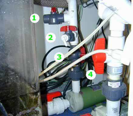
Pump Manifolds
Picture Taken December 2000 Pictured left was the water distribution system I used to use.
|